Heat Exchanger: |
Corrosion & Failure |
Shell & Tube |
|
|
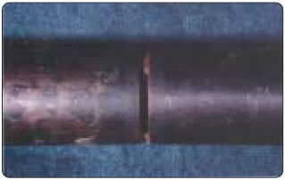
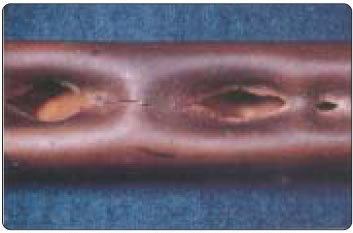
metal Erosion:
Fluid velocity in excess of the manufacturer recommendation on either the shell or tube side of the heat exchanger will likely cause erosion damage as metal wears from the tubing surfaces. If any corrosion is already present on the exchanger, the erosion is accelerated, exposing the underlying metal to further attack without a protective coating. A metal erosion problem most often occurs inside the tubes, along the U bend and near the tube entrances. Figure (A) is an example of metal loss in a section of U bend caused by extremely high-temperature water flashing over to steam.
Likewise, tube entrance areas often experience severe metal loss when a high-velocity fluid divides among the smaller tubes upon entering the heat exchanger. When a single stream divides into smaller streams, turbulence results with a very high localized velocity. It is this high velocity and turbulence that produces a “horseshoe” erosion pattern at the tube entrance.
The maximum recommended tube and entrance velocity is a function of many variables, including the material of the tube, fluid involved, and temperature. Materials including steel, stainless steel, as well as copper-nickel typically withstand much higher tube velocities than standard copper alone. A pure copper tube is normally limited to less than 8 FPS; other materials can handle upwards of 10 or 11 FPS. If the fluid contains suspended solids or for example, soft water, the velocity should be less than 7 ½ FPS. Less typical is erosion problems on the shell side of the tubes; typically erosion in this area is a result of impingement of wet, high-velocity gases, including steam. To mitigate this, wet gas impingement is controlled by designing an oversized nozzle inlet nozzles, or baffling the inlet nozzle. |
|
Steam or Water Hammer:
Pressure spikes, surges or shock waves as a result of a sudden and rapid acceleration or deceleration of any liquid can cause damaging steam or water hammer to the exchanger. Pressure surges have been seen in levels in excess of 20,000 psi, which would result in the complete rupture or collapse of the tubing of a heat exchanger. As an example, drawn copper 3/4 in. x 20 BWG tubing typically has a rated burst pressure of 2100 psi, along with a collapse pressure of 600 psi.
Pressure surges can be a result of an interruption in cooling water flow, stagnant water heated with a resulting generation of steam, or a resumption of flow producing steam. All these processes would likely cause a pressure surge, steam or water hammer. Therefore, the flow of the cooling fluid should always start prior to adding the heat load.
 |
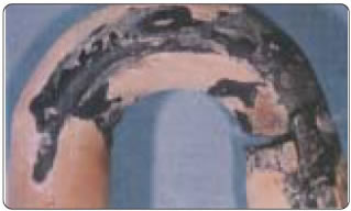
Control valves that open or close suddenly to control fluid flow can produce water hammer. A modulating control valve is a preferable option to “on-off” types. A vacuum breaker vents are a must if the process involves a fluid that can or may condense on either the shell or tube side. Vacuum breakers prevent steam hammer from developing and causing damage as a result of condensate accumulation. Figure (B) is an example of typical tube damage caused by steam hammer. In the example provided, condensate accumulated in the shell rapidly, producing a high pressure shock wave that subsequently collapsed the tubes and caused multiple tear holes. Correctly sized steam traps with installed return lines pitched to a receiving container for condensate or a condensate return pump should be installed as to prevent such damage. |
|
Vibration:
Excess ‘environmental’ vibration from equipment including air compressors, refrigeration machines or other motors can cause tube failures that form as a result of fatigue stress cracks and or erosion where the tubes make contact with the baffles. Ideally, heat exchangers should be isolated from all forms of vibration.
Fluid velocities that exceed 4 FPS could cause vibration induced damage in the tubes, often causing baffle supports to cut into the tubes (Figure C). Velocity-induced vibrations may also cause fatigue failures by hardening the tubes at the contact points between baffles or in U-Bend segments, eventually leading to cracks and splits.
|
|
Thermal Fatigue:
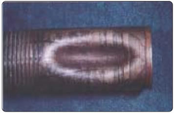
Tubes, predominantly in the U-bend sections, can fail as a result of fatigue from accumulated stresses related to constant thermal cycling. This problem is significantly aggravated as the temperature difference across the U-bends increase.
Figure D is an example of typical thermal fatigue. Temperature differences caused tube flexing, which subsequently produced a stress load that, until the materials tensile strength was exceeded and therefore cracked. The resulting crack most commonly runs in radials around the tube, and may result in a complete failure. |
|
Thermal Expansion:
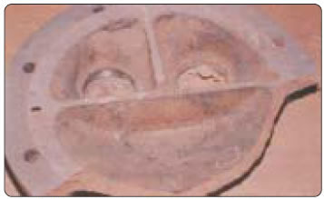
Thermal expansion failures are commonly found in exchangers involving exchangers; however, they may occur in most any process in which a fluid being heated is turned off without a provision for absorbing the subsequent thermal expansion.
In systems that involve steam heating, the cool down or condensing of residual steam on the shell side after the steam control valve closes will continue to heat water or other such fluids on the tube side. A resulting heat load with nowhere to go will cause thermal expansion, creating pressure well in excess of the tube, tube sheet, cast head, and component strength. Cast heads made from iron will fail due to lack of ductility; steel tube sheets will bow or become distorted permanently because the material yield point is exceeded. Figure (E) is an example of thermal expansion and failure of a cast iron head.
Relief valves are often installed in the fluid being heated to prevent a failure of this sort. Manufactures commonly install and or advise for a means to absorb fluid expansion.
|
|
Freeze-up:
A freeze failure is most commonly found in condensers or evaporators; however they can occur in any process where a temperature drop below the freezing point of a given fluid exists. Typical freeze-ups are a result of the operator failing to provide thermal protection from the elements, improper drainage during a seasonal shutdown, malfunction of a thermal protection system or heater, or inadequate antifreeze solutions.
As an example, let’s assume a chiller has been improperly set or its controls are malfunctioning allowing water to cool below the freezing point. As ice crystals form, they exert tremendous pressure in the tubing, causing it to rupture and or collapse. Figure (F) is an evaporator, with a tube near the tube sheet where it was inadequately protected.
Freeze-up failures in a condenser application may also occur when cooling water is circulating inside the tubes and refrigerant on the finned surfaces was not aquatically drained for winter shutdown. Refrigerant pressure from the condenser is suddenly released as a result of a line break or relief valve discharge dropping the pressure below the refrigerant boiling point. The boiling process then extracts heat from the water in the tubes causing a freeze up. |
| |
|
|
|